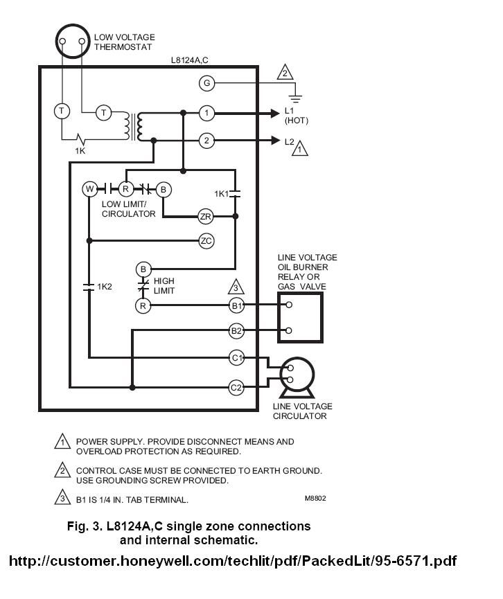
The l8148e,j can power up to two v8043 zone valves. Honeywell aquastat l8124c users manual 95 6571 l8124a,c,e,l and m usermanual.wiki.

Wiring diagram honeywell aquastat thermostat coleman mach rv relay lovely schematic wire unit air data heat stage btu mastercool circuit.
Honeywell aquastat l8148e wiring diagram. Wiring l8148e with multizone valves. The l8148e,j can power up to two v8043 zone valves. Tab terminal connector, use 18 to 22 gauge wire with amp inc.
La,e,j aquastat® relays t87f t87f t87f r r r relay pump pump. Aquastat relay le problem wiring lighted doorbell button honeywell aquastat relay le wiring snatch block diagrams wiring low voltage. Relay moreover honeywell le wiring diagram as.
Aquastat honeywell wiring doityourself dscf0447. When wiring a switch equipped with 1/4 in. Wiring diagram honeywell aquastat thermostat coleman mach rv relay lovely schematic wire unit air data heat stage btu mastercool circuit.
Additional valves, in groups of two or fewer, require an additional transformer. A remote low limit controller can be added. Honeywell aquastat l8124c users manual 95 6571 l8124a,c,e,l and m usermanual.wiki.
Wiring l8148e in multizone system with r882c switched circulator. This video demonstrates basic wiring of an l8148 aquastat. Wiring l8148e with s8610 automatic vent damper plug and vent damper.
1.2a load is the maximum permissible when ambient temperature exceeds 77°f (25°c). Honeywell aquastat relays manual users. Its high limit opens the burner circuit only.
B number of v8043 zone valves that can be powered from the l8148 without additional transformer(s). Wiring l8148e1265 with internal plug directly to vent damper in hydronic intermittent pilot system. The controller switches both burner and circulators.