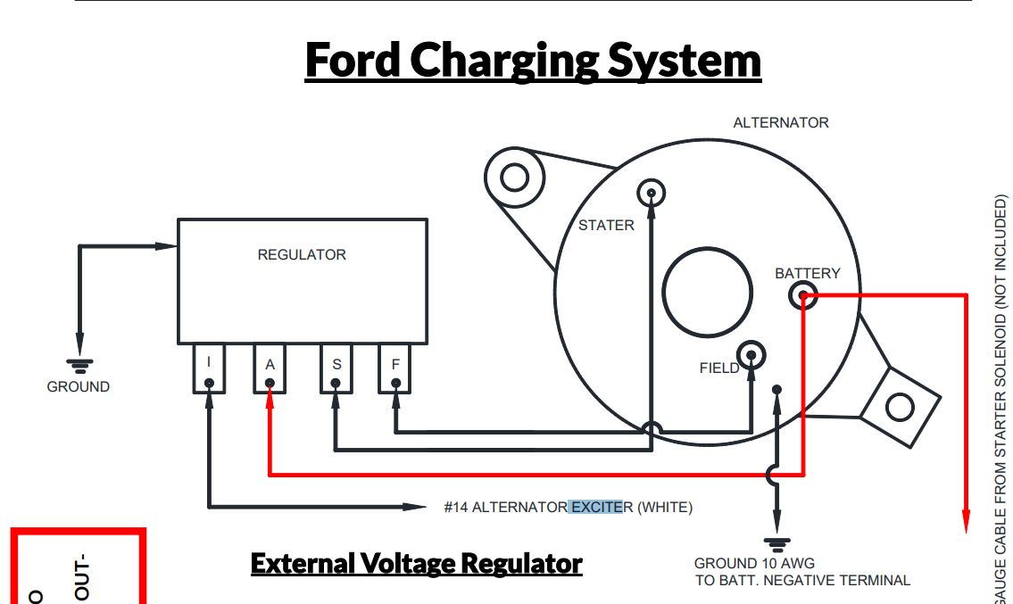
When you employ your finger or even follow the circuit together with your eyes, it may be easy to mistrace the circuit. Here�s a pic of a �79 wiring diagram to aid you with what that year harness.

Print the cabling diagram off and use highlighters in order to trace the routine.
Ford voltage regulator wiring diagram. This is from a 1985 ford f350 with the 6.9l diesel engine. I believe these type regulators were very common in the �80s. External voltage regulator wiring diagram 1988 f150 we fabricated an orthodontic appliance for rats from bent ni ti wire.
For instance , if a module is usually powered up and it sends out a new signal of half the voltage and the technician will not know this, he would think he has a challenge, as he would. This voltage varies with the ambient temperature i just did this swap on my �80 sc diagrams and such: Ford voltage regulator wiring diagram.
Connects to the field terminal on the alternator. Alternatively, you could run a single 6 gauge cable and replace the original wire entirely For example , in case a module is powered up and it sends out a new signal of half the voltage in addition to the technician would not know this, he�d think he has a problem.
Wiring diagrams & harnesses for ford tractors author: Ford external voltage regulator wiring diagram from www.sbmar.com. External regulator 3 wire ford alternator wiring diagram from ls1tech.com.
Allows battery voltage from the ignition to flow to the alternator’s field coil during startup. To properly read a cabling diagram, one has to learn how the components in the method operate. Prestolite voltage regulator wiring diagram.
For the four wire regulator: 1 trick that i 2 to print out the same wiring diagram off twice. In todays video we cover how to diagnose a first gen ford alternator and test the alternator or voltage regulator.tools used in the videovolt meter:
Connects to the battery positive post on the solenoid switch. Here�s a pic of a �79 wiring diagram to aid you with what that year harness. Connects to the ignition circuit.
Neil reitmeyer, rob g, don & derek barkley, dan dibbens, ed gooding, and tyler neff Allows the regulator to sense the battery’s voltage. Electronic voltage regulators have been used on many cars since the mid 1970s.
Most of the wiring diagrams posted on this page are scans of original ford diagrams, not aftermarket reproductions. And also the internal wiring diagram for the alternator that went along with it (model ??). Wiring of an old ford truck externally regulated alternator.
Where can i find the internal schematic for the common ford external alternator regulator, the one with i a s f terminals? Wiring diagram voltage regulator please see the picture, 1972 ford regulator wiring diagram span class news dt apr 13 2009 span nbsp 0183 32 1961 1966 f 100 larger f series trucks 1965 wiring diagram anyone have a decent wiring diagram Ford alternator and an ext voltage wiring with without the regulator w external troubleshooting gm internally regulated electrical 12 volt diagrams regulation 101 g series 12v externally another conversion identify my vintage wire harness installation instructions dodge help 1947 present testing delco 10dn 7000 chrysler negative autolite truck.
Points coil 12v dash panel ammeter terminal block 4— key switch starter button chas�s grd strap single wire alternator \ 1952. To properly read a electrical wiring diagram, one offers to learn how the particular components in the system operate. Print the cabling diagram off and use highlighters in order to trace the routine.
Generator to alternator conversion diagram and tec tips. When you employ your finger or even follow the circuit together with your eyes, it may be easy to mistrace the circuit. The generator (alternator) output is supplied through the battery positive voltage (b+) output connection to the battery and electrical system.
Connects to the stator terminal on the alternator and electric choke on the carb.