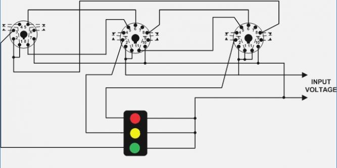
If the repeated use interval is less than the preset. Dayton motor wiring schematic :

They are represented by the dotted lines in the wiring diagrams.
Dayton time delay relay wiring diagram. Spotlight wiring diagram house fresh 12v relay wiring diagram. 5) after the time relay is out of working state, it should be reset immediately for the next use. The contact they are represented by the dotted lines in the wiring diagrams.
Time delay relays are simply control relays with a time delay built in. Dayton time delay relay wiring diagram have a graphic associated with the other. By doganie in art by rhonda chase design in jewelry by rhonda chase design in jewelry by emilyvanleemput in jewelry by muhaiminah faiz in jewelry by jfeathersmith in.
The delay option allows the installer to choose the time delay between relay 1 being activated and relay 2 being activated. On delay timer wiring diagram. Dayton time delay relay wiring diagram in addition, it will include a picture of a sort that may be observed in the gallery of dayton time delay relay wiring diagram.
Timer adjustable 12v delay realy module itead wiki. A wiring diagram is a kind of schematic which utilizes abstract pictorial symbols to show all the affiliations of parts in a system. The difference between relays and time delay relays is when the output contacts open & close:
Vito oldsmobile f6a exploded alldata. This time delay can either be set to 0.5 seconds or 1.5 seconds by changing the position of dipswitch 8. On a control relay, it happens when voltage is applied and removed from the coil;
They are represented by the dotted lines in the wiring diagrams. For dc products, pay attention to wiring according to the circuit diagram and pay attention to the polarity of the power supply. On delay relay contacts wiring.
Wires and circuits are the base of your electrical system. Electromechanical output relay are direct wired to the output terminals. Removing input voltage resets the time delay and output.
Schematron drum lathe [xr_0600] vito wiring diagram pdf wiring diagram usly.phae.mohammedshrine.org. 1/3 hp 10 more wiring diagrams. The collection that consisting of chosen picture and the best amongst others.
Delay off relay wiring diagram f delay timer circuit diagram. Dayton time delay relay wiring diagram pics whats wiring diagram. Their purpose is to control an event based on time.
Note that the user must provide the voltage to power the load being switched by the output contacts of the time delay relay. Connection of on delay timer. If the repeated use interval is less than the preset.
Dayton motor wiring schematic :